The case usually has a sticker with a red arrow on it that says "Ribbon Cable Red Stripe" ( it is on the side of the DC power connector). However to use a standard 50 pin ribbon cable you have to trim the key off. For some reason they did their cables backwards from computers with respect to keying. Perhaps to force you to buy theirs.
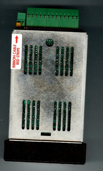 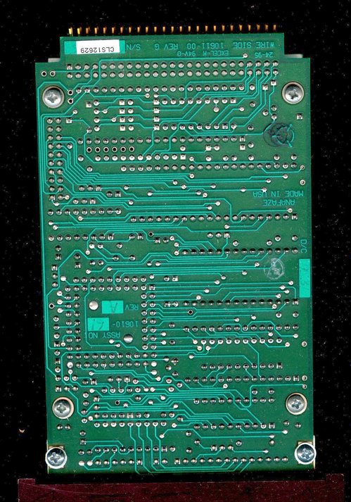 
Pin #1 of the output signals is on the lower row towards the side with the red arrow. The square PCB pad is pin#1
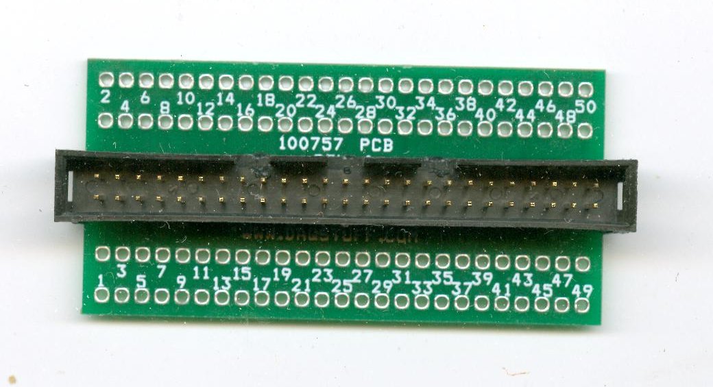
Again the key needs to be trimmed off a standard cable to match the backwards cable design of the Anafaze controller. The red stripe on the cable goes towards the left side where the pin labeled "1" is.
 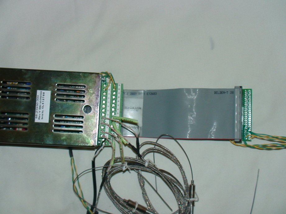
Breakout board after being wired for CLS04. Photo to the right shows orientation of the mated system. Red stripe on ribbon cable goes to pin #1 on the controller and on the breakout board.

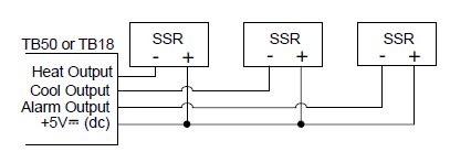
The Anafaze output drive is a "low side switch". You can imagine it working exactly like a light switch that is between the negative pole of a battery and ground. When the switch is open no current flows. When the switch is closed current flows. However if you read the voltage on the output pin it will appear backwards. You will read 5 volts when the output is off and 0 volts when it is on. That is because your volt meter would read the voltage of the other side of the load since no current is flowing and it is still connected. See the diagram above.
The digital outputs sink current from the load to the controller common. The load may powered by the 5VDC supplied by the controller at the TB50. Alternately, an external power supply may be used to drive loads. Keep in mind the following points when using an external power supply:
- The CLS200 power supply available from Watlow Anafaze includes a 5VDC supply. When using it to supply output loads, connect the 5VDC common to the 15VDC common at the power supply.
- Do not exceed +24 volts.
- If you tie the external load to earth ground, or if you cannot connect it as shown in (See Figure 2.22), then use a solid-state relay.
All digital outputs are sink outputs referenced to the CLS200 series controller common supply. These outputs are low (pulled to common) when they are on. The outputs conduct current when they are low or on. The maximum current sink capability is 60 mA at 24VDC. They cannot “source” current to a load.
You can test your understanding by looking at the diagram below.
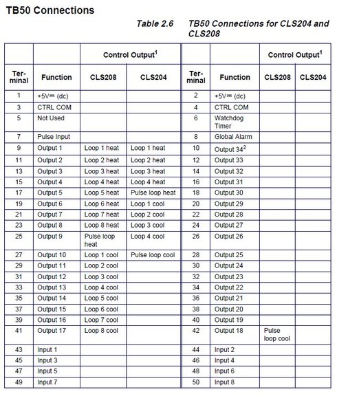 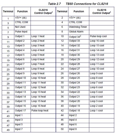
The pin outs of the Anafaze CLS04, CLS08 ( 4 and 8 channel units ) Pinouts of the CLS16 ( 16 channel unit )
Thus for example to wire the outputs for channel 1 through 8 of a CLS08 you use: Pin# 9, 11, 13, 15, 17, 19, 21, 23 on the low side = negative input terminal of your switching device. If you understood the above you know that all the high sides are connected to +5 Volts DC on PIN #1 ( or pin#2). These numbers correspond to the numbers on the small green PC board.

DAQStuff also has a screw terminal breakout for higher end realizations:

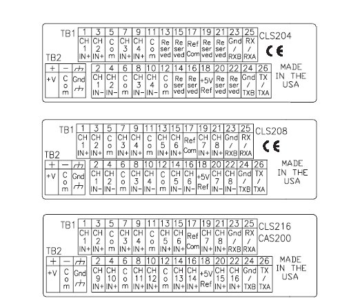
The inputs are alot easier to wire. Just add thermocouples per the call outs below.
|